
We then have our first RC network, composed of a resistor and capacitor. So our input signal to the circuit is a square wave. Will work square wave signals at or above 10KHz. So this circuit, with the given value capacitors given below, The frequency of the signal and the capacitor values needed in more detail below.įor this circuit, we will input a 50KHz signal. The capacitors had no effect on the signal because the value of them are out of the frequency range. If not, the same square wave signal that we feed into the circuit will be output, meaning If the capacitor value isn't appropriate for the frequency of the square wave signal, the circuit will not work. The capacitor values that we choose for the circuit is based off the frequency of the input square wave So a total of 2 resistors and 2 capacitors are needed for this circuit.Įven though this circuit is very basic in that it only requires 2 resistors and 2 capacitors, it doesĬontain some complexity in regard to the values of the resistors and more importantly the capacitors in regard to the Each RC network is comprised of 1 resistor andġ capacitor. In fact, to build this circuit, we only need 2 RC networks. And this can be accomplished rather easily with just resistors and
#Squarewave in pspice schematics how to#
How to convert a square wave to a triangle wave. Even though triangle wavesĪre used much less frequently, in certain cases such as acoustics, they may be needed. Many types of digital devices output square waves. Using RC networks, we can reshape aĪ circuit is like this can be very important because square waves are commonplace in electronics. To do so, we simply need resistors and capacitors- nothing else. In this project, we will show how to build a square wave to triangle wave converter. Obtain the response for following RL combination R = 68 2 and L = 2.2 mH.How to Build a Square-to-Triangle Wave Converter R = 100 2, L = 1.0 mH R = 2202, L = 1.0 mH L V1 R W1 2.5 Figure 3 - RL circuit with square wave input. Calculate the time constants using the circuit parameters. Note that the response changes by a factor of 1/e during one time constant. From the transient response plot determine the time constant. Obtain the response for the following two RL combinations (simply change R and repeat). Limit your transient response plot to one cycle of the source voltage. Use PSpice to determine the natural response (voltage across the resistor) of the circuit.

Again, create the waveform so that the pulse width is half the period. What do you notice about the transient response? How is it different than the above combinations? The circuit of Figure 3 is excited by a square wave voltage of 4 V peak (zero to peak) as before, but now with a frequency of 5 kHz.


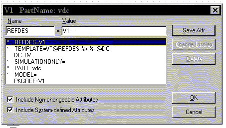
R V1 с W1 Figure 2 - RC circuit with square wave input.Ģ.3 2.4 Obtain the response for following RC combination R = 3.3 k2 and C = 0.47 uF. Calculate the time constants using the circuit parameters.Note that the response changes by a factor of ile during one time constant. From the transient response plot determine the time constant.Obtain the response for the following two RC combinations: R = 3.3 k12, C = 0.1 uF R = 3.3 k2, C = 0.22uF This may be done by setting the "Run to time" parameter in the "Edit Simulation" window to be of the same length as the period of the VPULSE. TR PW TF V1 V2 TD PER Figure 1 - PSpice implementation of a square wave Use PSpice to determine the transient response (voltage across the capacitor) of the circuit. Set the other parameters of the waveform as indicated in Figure 1. In PSpice, use VPULSE to create this voltage waveform by setting V1 to 4 and V2 to 0. The circuit of Figure 2 is excited by a square wave voltage of 4 V (zero to peak) having a frequency of 100 Hz. Transcribed image text: 2.1 2.2 The PSpice presentation will be useful for your prelab study.


 0 kommentar(er)
